More Stateroom Storage Space
Open up storage space under your bed!
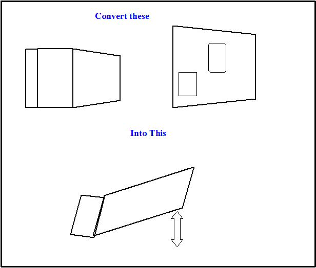
Convert your bed deck to a Lifting Hatch with Gas Spring assist!
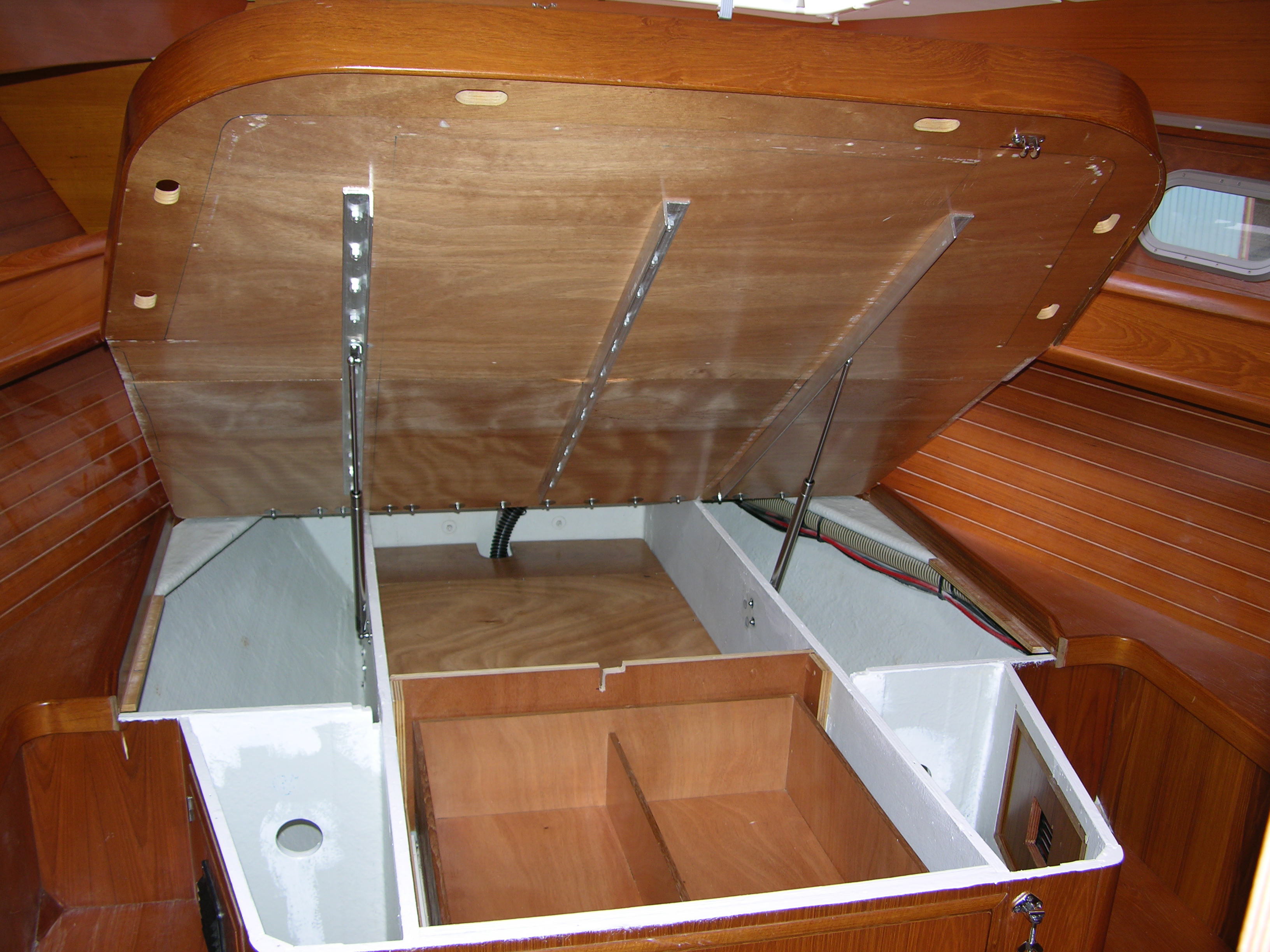
Many bed decks on boats and RV’s have two or three pieces of plywood secured to the hull and vertical bulkheads. The stateroom storage space under the bed deck is difficult to access and therefore goes unused. By converting the pieces into a lifting hatch system, all that space is instantly accessible. With gas springs on the bed deck, the whole bed deck and mattress are easily lifted by anyone. (Images at bottom of the page)
The details of these instructions are for Jeanneau SO 45.2. The concepts may work for your boat as well. Once you have modified schematics for your system, Atwood Marine may be very helpful. They will calculate the model of gas springs as well as the exact position of their mounts.
Figure 1: Bed with Lifting Deck. Schematic scale: ½ inch = ~ 10 inches

| Start Angle : |
0.0 Grad |
Opening Angle : |
38 Grad |
| Handle Radius : |
60.0 inch |
Weight Radius : |
30.0 inch |
| Weight of Aft Lifting Section, mattress and bedding: |
~ 110 lb |
| Attachment Point |
X [inches] |
Y [inches] |
| Moving : |
35.0 |
-1.0 |
| Fixed : |
18 |
-3.5 |
Definitions
Start Angle: The angle across the hinge in the resting/ closed position. (Zero most cases.)
Opening Angle: The maximum angle at the hinge when the Aft Lifting Section is fully open.
Handle Radius: The distance from the hinge to the very end of the Aft Lifting Section.
Weight Radius: The center of the weight on the Aft Lifting Section. In most cases this will be the center of the Aft Lifting Section.
Attachment Points: Placement of the “mounts” that connect the gas springs to the Bulkheads and Aft Lifting Section. The hinge is the “zero” point for X direction (horizontal). The bottom plane of the Aft Lifting Section is the zero plane for the Y direction (vertical).
Moving: The attachment point of the mount on the frame of Aft Lifting Section.
Fixed: The attachment point of the mount on the bulkhead.
Summary of lifting bed deck
Introduction:
The original ¾ inch thick plywood bed deck was securely screwed down to the bulkheads (vertical walls that support the bed deck and contain the water tank). It was a sturdy design but it was difficult to access storage areas and the water tank. The plywood sections were converted into a semi-stationary forward section and an aft hinged hatch with gas springs to do the heavy lifting. The bed deck may still be screwed down for heavy weather sailing.
Summary
The original bed deck was in three pieces. In these instructions, they are identified as the Forward Section, Center Section & Aft Section. The Forward Section was converted into the Semi-Stationary Forward Section with a piano hinge connecting it to the new Aft Lifting Section. The new Aft Lifting Section was converted from the two remaining pieces, Center & Aft Sections. The gas springs were attached on the bottom to the bulkheads and on top to the frame of the new Aft Lifting Section.
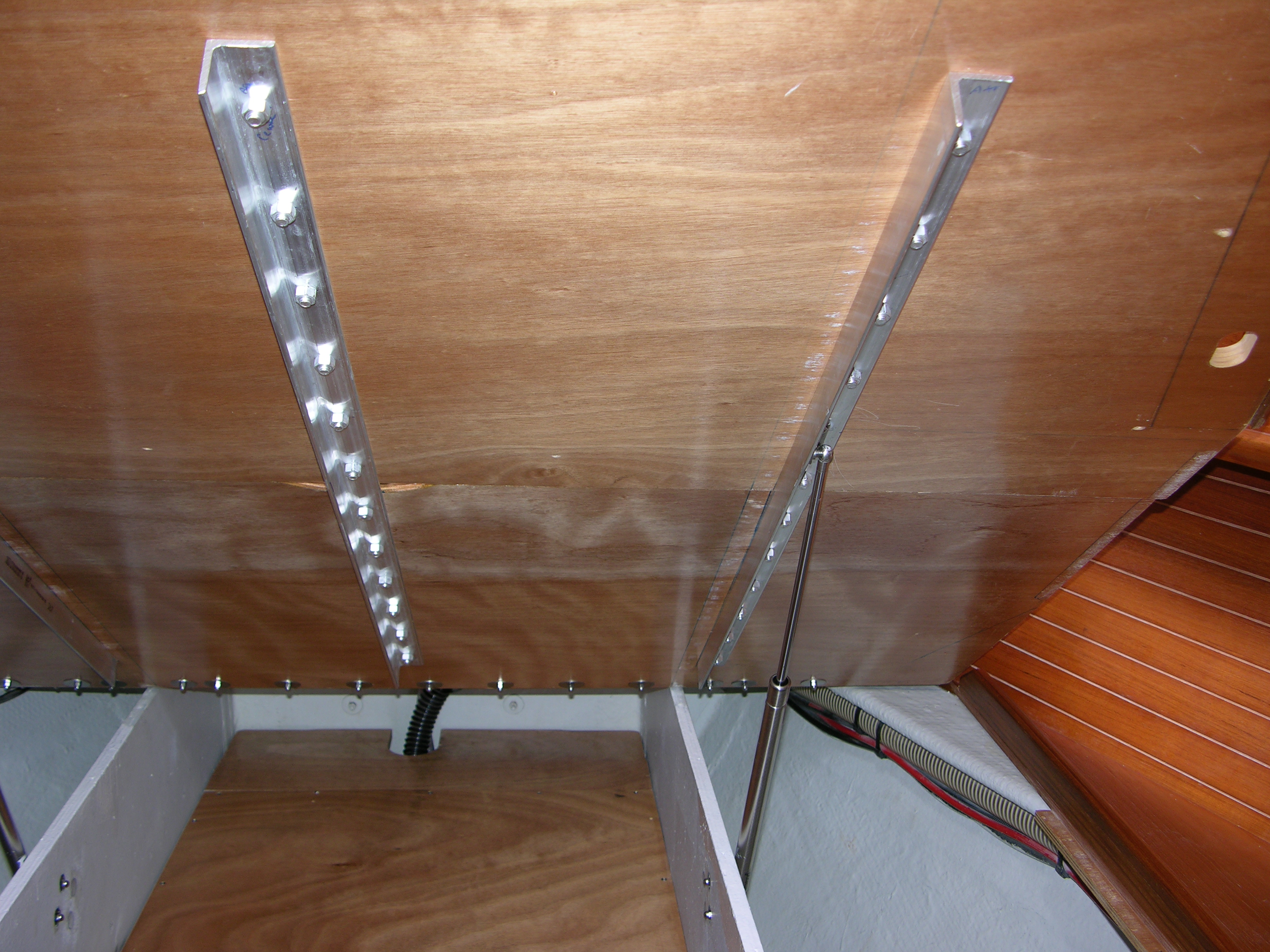
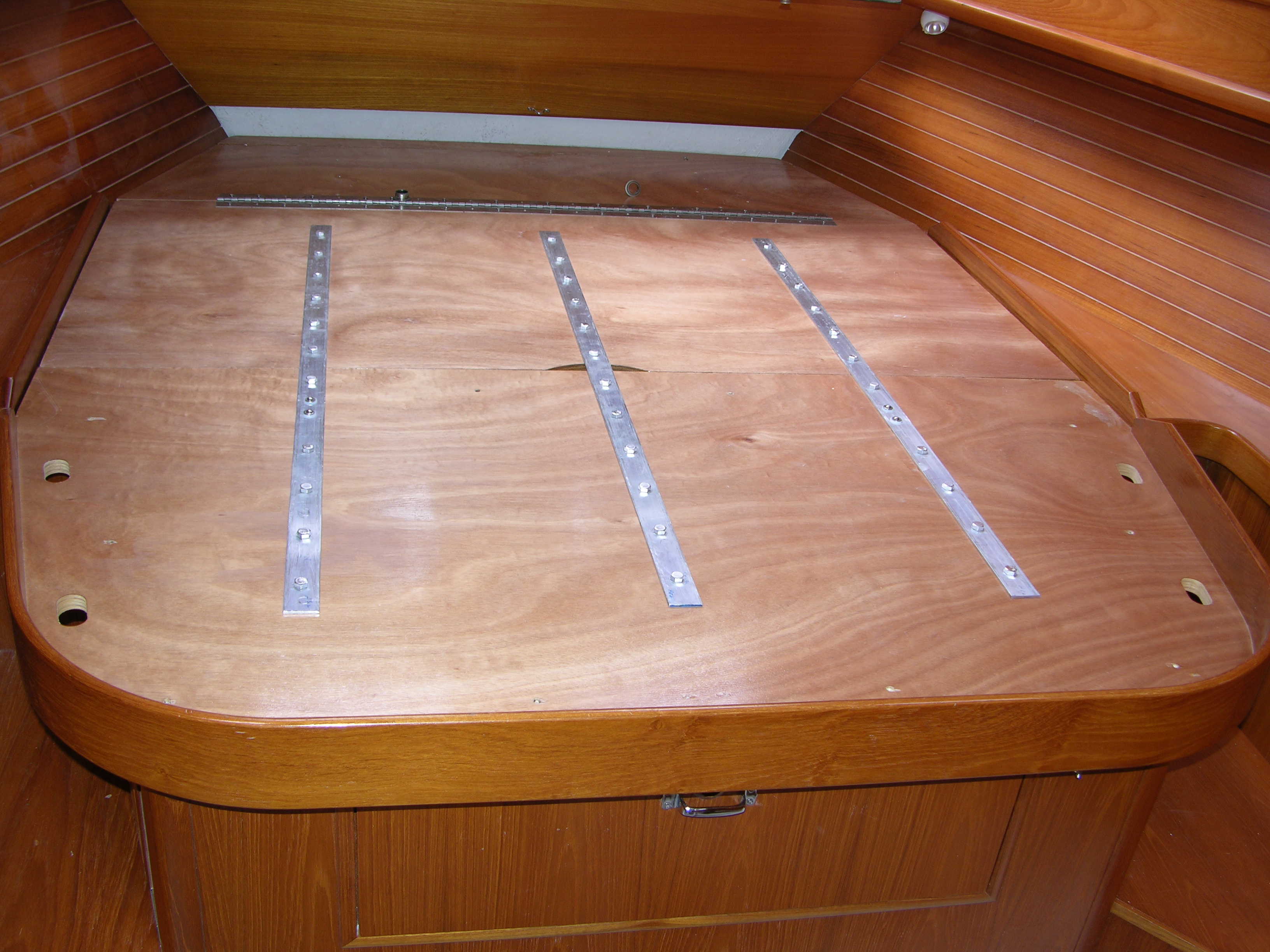
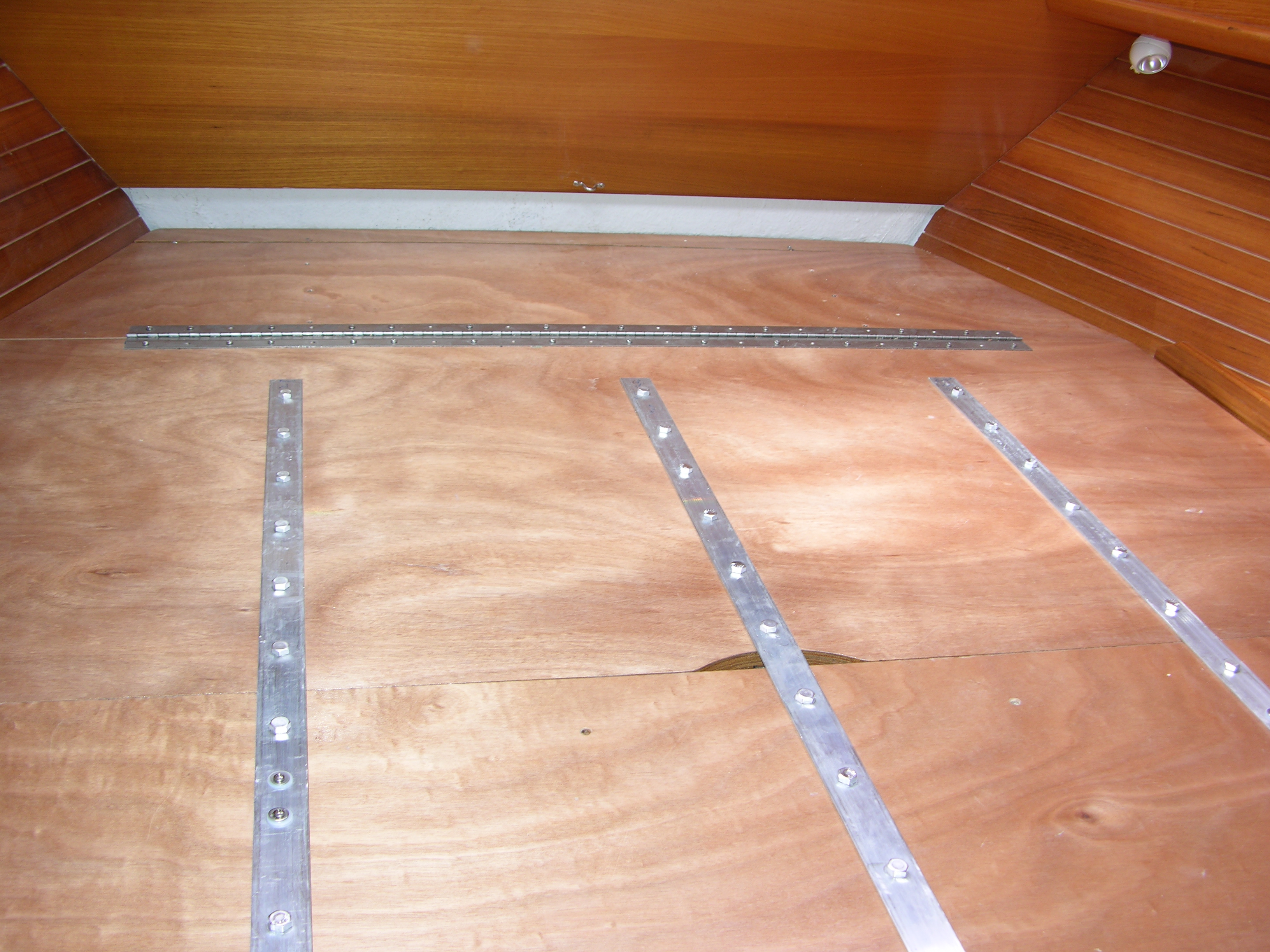
The Center & Aft Sections of the bed deck are converted into one piece using aluminum straps above and below the union of the two pieces making them securely operate as one piece. The straps above are flat bars and angle bars below, held together with aluminum bolts every four inches.
Once the gas springs are attached, the Aft Lifting Section (deck) is easily lifted for access to all that storage space. A latch is used to secure the end of the Aft Lifting Section in the closed position.
Semi-StationaryForward Section of bed deck is screwed to the bulkheads. For access under it (water tank fittings), a little more effort is necessary. First, securely screw down the Aft Lifting Section. Second, unscrew the Semi-Stationary Forward Section. Now it may be opened on the piano hinges.
A stationary forward plywood strip (2 ½” wide) is cut from forward part of Forward Section and permanently screwed to vertical bulkheads. The purpose of the spacer is to locate the forward edge of the Semi-Stationary Forward Section aft two inches. This allows the Semi-Stationary Forward Section to be lifted and clear the inward slanting bulkhead at the head of the bed.
Parts Required for Converting Bed Deck
Original construction of the bed deck on the Jeanneau Sun Odyssey 45.2 is made of ¾ inch plywood and cut into three sections. Each section is screwed into the vertical partitions (bulkheads) beneath the bed deck. The partitions contain the water tank and strengthen the hull. In addition, the space provides significant storage space. For these instructions, the plywood sections are referred to as:
Forward Section: 18”, (fore and aft dimensions) Center Section; 30”, Aft Section; 35”
Tools & Supplies: Drill and bits, skill saw, jig saw (table saw), router, grinder, carpenters square, work bench and C clamps, wrenches & drivers, screw drivers, metal files, sand paper, tape measure, interior hull paint, duct tape(of course), assorted Stainless Steel (SS) wood screws and bolts and nuts and washers and plastic insulating spacers
Aluminum straps/supports bridging the union of bed deck Center & Aft Sections.
- Three Angle (L) bars below and three flat bars above
- Each bar is 48 inches long
- Flat bar is 1/8” thick, 1 ½” wide
- Angle bar is 3/16” thick and 1 ½” wide
- Aluminum bolts and nuts
- AL hex head bolts are 1 ½ inches long and 3/8 inch OD
- Bolting Angle bar and Flat bar together with plywood sandwiched in-between
SS Piano hinge at union of Aft Lifting Section and Semi-StationaryForward Section.
- SS bolts: 1 ¼ inch long; counter sunk head; cross-recessed; 3/16 inch OD; fine threads;
- Acorn nuts (capped nuts); SS pan washers on under side
T-Bar Hatch Fasteners (West Marine Part #: 7219116) to secure Aft Lifting Section down
Gas Springs from: Attwood Marine 1016 N Monroe, MI 49331 616-897-9241
John Holtforth, Product Development Engineer john.holtforth@attwoodmarine.com
(2) Stainless Steel Gas Spring Part # SS25-130-1 (130 is force in pounds) ~ $ 100 ea
(2) Bed deck mount Part # SL58P3R-7 ~ $ 10 a pair
(2) Bed support mount Part # SL 40 SS P3 – 7 ~ $ 10 a pair
SELECTED GAS SPRING Quantity : 2
F1: 130 lb; 10 mm rod; 22 mm cylinder; End fitting type: 10 mm socket – SS metal
| Gas Spring Lengths |
Extended [inch] |
Stroke [inch] |
Compressed [inch] |
| Nominal: |
26.3 |
10.2 |
|
| Actual: |
26.3 |
9.1 |
16.1 |
Lifting Bed Deck Assembly Instructions
The following instructions guide work on the listed parts and the schematic in Figure 1 to convert the bed deck on the Jeanneau Sun Odyssey 45.2 into a lifting hatch for easy access to the storage space beneath. The order of these steps are specifically designed to help it go easier and faster.
Piano Hinge placement between the Forward and Center Sections
The first step is to simply line up the SS piano hinge over the union of the Forward and Center Sections and drill the holes in the plywood to match those predrilled on the hinge. Screw the Forward Section to the bulkheads using existing holes.
- Lay the Center Section snugly against the Forward Section.
- Align for proper clearance on either side of the Center Section
- Position the piano hinge and mark the bolt holes on both plywood sections & remove the hinge.
- Drill holes; alternate holes; skip holes directly over the vertical partitions (bulkheads supporting bed deck) & drill holes on either side
- Temporarily bolt piano hinge; first to the Forward Section and second to the Center Sections:
- SS bolts: 1 ¼ inch long; counter sunk head; cross-recessed; 3/16 inch OD; fine threads;
- Acorn nuts (capped nuts); SS pan washers on under side
- Check the hinge for smooth lifting action
- Unbolt the hinge from the Forward Section & permanently bolt the Center Section
- Remove wood screws holding the Forward Section to the bulkheads.
Cutting and securing the Stationary Forward Strip
A stationary forward plywood strip (2 ½” wide) is cut from forward part of Forward Section and screwed to vertical partitions below. This allows the Semi-StationaryForward Section to be lifted and clear the inward slanting bulkhead at the head of the bed.
- With the Forward Section properly placed, mark the position of the aft edge on the bulkheads that it rest on.
- Using a table or skill saw, cut 2 ½ inches off the forward edge of the Forward Section to make a Stationary ForwardStrip.
- Drill pilot holes in the Stationary ForwardStrip for screwing to the bulkheads below. (SS wood screws, 1 ½” long)
- Permanently screw Stationary ForwardStrip in place firmly against the forward bulkhead.
- Make up the “saw blade space” cut from the Forward Section and adjust to achieve a square fit:
- Use the marks on the bulkheads, the Semi-StationaryForward Section and Center Section to test for a square fit and determine where to place the washers.
- Adjust the space and alignment with the thickness and placement of 3 or 4 stacks of ¾” wide SS washers. Once the appropriate thickness has been determined, permanently screw them onto the aft edge of the Stationary ForwardStrip.
- Drill two additional pilot holes (four screws minimum) in the Semi-StationaryForward Section for screwing to the bulkheads below.
- Screw the Semi-StationaryForward Section in place.
Aluminum bar “Strapping” for Center & Aft Sections
Hold the flat and angle bars in place on the Center & Aft Sections as well as on the bulkheads beneath it to visualize how they will work together.Remove the AL bars and place on a workbench. Using C clamps to hold the flat and angle bars in alignment, drill the bolt holes. Finishing the bars at this time allows for numerous measurements in the subsequent steps.
- Drill Bolt holes in angle and flat bars:
- Clamp the angle and flat bars together on a work bench.
- Drill 3/8” holes, 4” apart, starting 2” from the end. There should be 11 holes in port and starboard pieces, skipping the area directly over the athwartships vertical partition. There should be 12 holes in the center pieces
- Hint: After each hole is drilled, place a bolt through the bars to help hold there relative position.
- File burs from holes and round off edges of angle and flat bars
- AL hex head bolts are 1 ½ inches long and 3/8 inch OD
- Flat bar is 1/8” inch; plywood is ¾ inch and angle bar is 3/16 inch for a total just under 1 inch
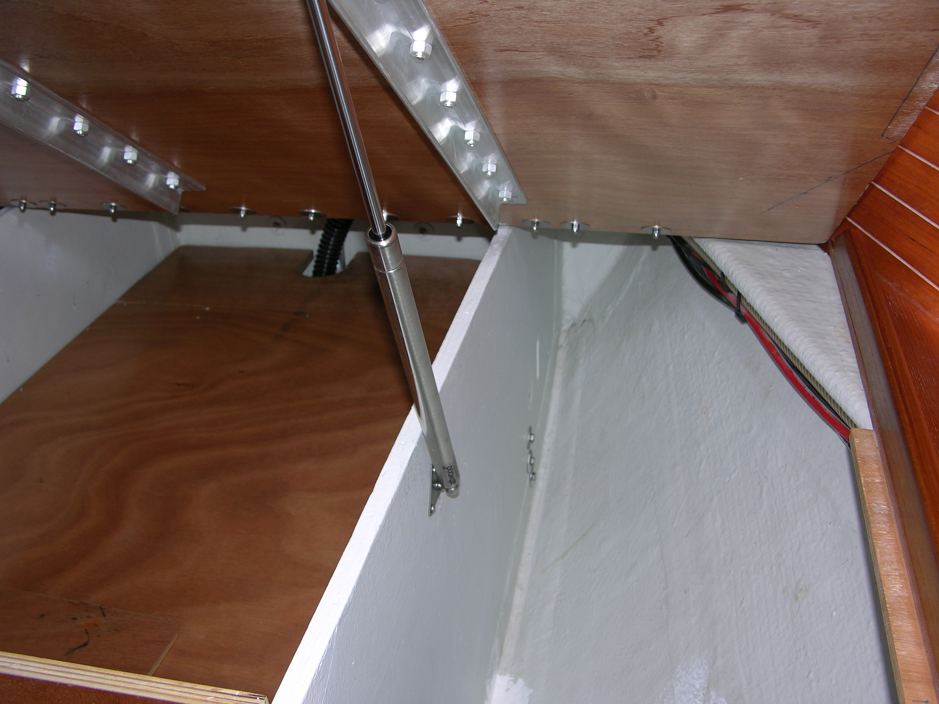
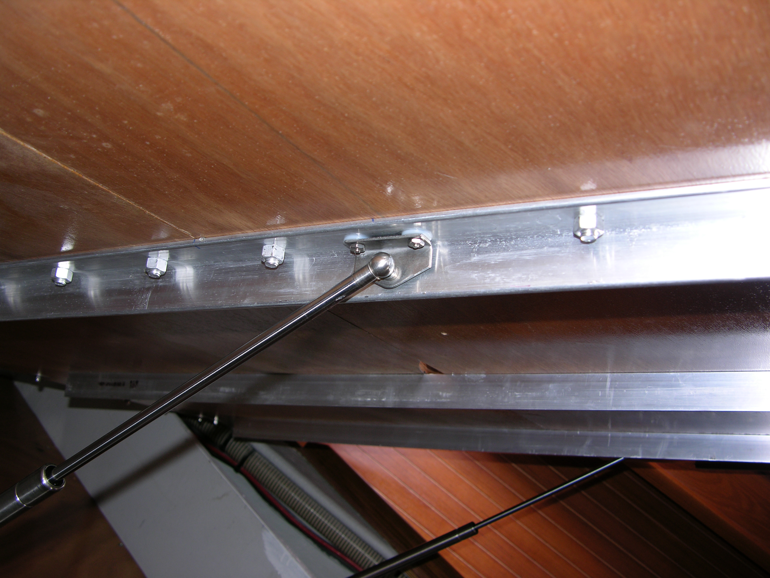
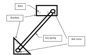
Lower Bracket mounting for Gas Springs (GS)
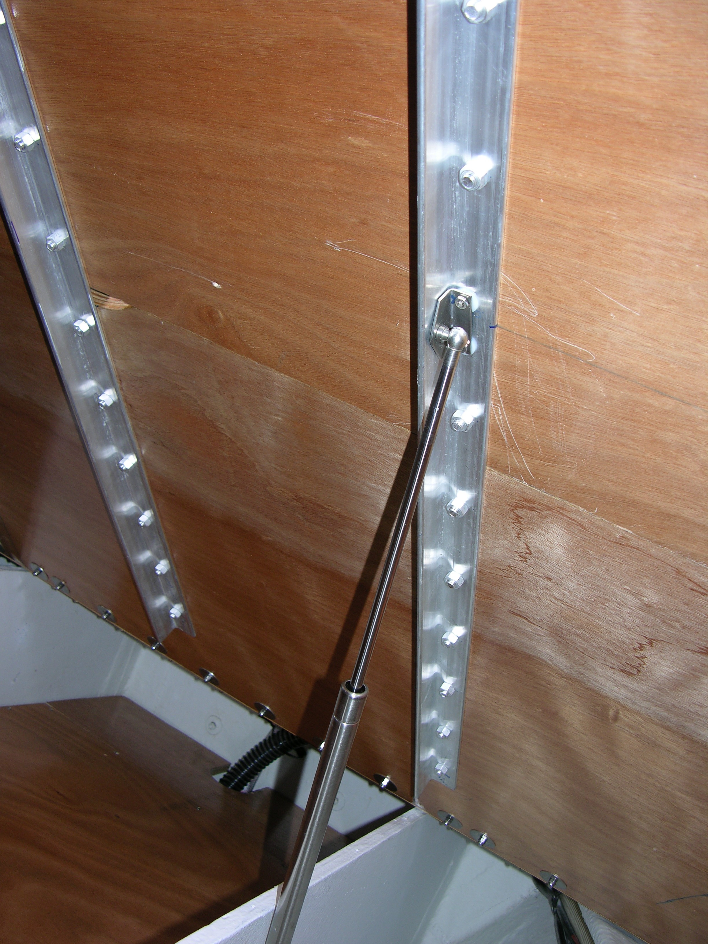
The gas springs are attached on either end via a ball joint. The ball is permanently attached to a bracket. Together, they may be referred to as a “mount.” Two mounts are attached to the frame of the Aft Lifting Deck and two to the bulkhead. The positioning of the mounts must be accomplished to place the ball joint in the prescribed relationship to the hinge and plane of the Aft Lifting Deck bottom. In other words, the X and Y values in Figure 1.
- Mark the positions on bulkheads (vertical partitions) for the lower GS ball joint.
- The ball joint is on the outboard side of the bulkhead.
- The brackets are bolted in place so that the ball joints are correctly positioned.
- See instructions from Attwood Marine with positioning instructions.
- The bracket with ball must be positioned so that the ball “catches” the force and is not “pushing” against it. In terms of directional force, the ball joints must be “downstream” of the mounting bolts.
- Drill holes in the bulkhead for the lower GS brackets and attach with thru bolts (counter sink on water tank side)
Figure 2. Brackets with Ball downstream of bolts
Cut channels in bulkheads for angle bars
The angle bars used to strap the Center & Aft Sections together will extend below the bottom plane of the bed deck. They lie on the outboard side of the ‘fore and aft’ bulkheads. The athwartshipsbulkheads must be cut to match the shape and location of the angle bars. There are three angle bars, however on the Jeanneau SO45.2, only the outboard angle bars interfere with a bulkhead.
- Place the angle bars next to the fore/aft bulkheads on the outboard side.
- Mark the striking positions of the angle bars on the athwartships bulkheads:
- Cut vertical slots (5/8” wide, 1 ½” deep) in the athwartships vertical partitions
- Use a router to trim the horizontal slot on the athwartships partition (1 ¾” wide, ¼” deep)
- Seal the bare edges of the exposed plywood with Epoxy
Drill holes in plywood for AL bolts
Carefully drilling the holes in the plywood Center Section will insure a strong and good fit. For the best results, use the bars with predrilled holes as templates. The C clamps work to hold the bars in place because only the Center Section isin place, leaving an open area where the Aft Section would have been. You can carefully align the bars to be centered across the union and keep the holes equal distanced from the union. The angle bar must fit the slots in the vertical partitions.
- Position the Center Section in place
- Temporarily bolt the piano hinge to the Forward Section
- Carefully align the angle and flat bars on the Center Section and clamp in place
- Drill 3/8 inch bolt holes in Center Section, using the flat bar holes as templates
- Drill first hole at the forward end and bolt the angle and flat bars in place, use a C clamp on other end and drill the remaining holes.
- Place a bolt in each hole immediately after it is drilled
- Remove angle and flat bars to allow for dust and shaving clean up
Assemble Forward and Center Sections
- Permanently bolt the angle and flat bars to the Center Section.
- Permanently Bolt the piano hinge to the Forward Section.
- Screw Forward Section in place with wood screws.
Drill Holes for Aluminum bar “Strapping” in the Aft Section
The Aft Section hole drilling will be more challenging because it is more difficult to reach the top and bottom sides at the same time. A helper is suggested. The bed deck should be raised slightly and held in place with a sturdy prop while the holes are being drilled.
- Slide the Aft Section between the angle and flat bars and align for proper clearance on either side of the Aft Section
- Drill the 3/8” bolt holes in Aft Section using the flat bar holes as templates
- Drill first hole at forward end
- Place a bolt in each hole immediately after it is drilled
- Remove the Aft Section
Upper Bracket mounting for Gas Springs (GS)
The upper bracket for the GS is another challenging task. The bracket is bolted vertically through both bars and the plywood. Drilling holes through both bars is best done without theplywood Aft Section in place. Use a spacer on either side of the bracket instead. Again, the proper placement of the ball joint in the X and Y planes is vital.
- Carefully determine the proper placement of the ball joint in relation to the angle bar.
- Mark upper GS bracket bolt hole positions on the angle bars from bottom side.
- Drill holes for upper GS brackets in angle and flat bars
- Insure a flat fit against under side of angle bar
- Drill hole from bottom, thru angle bar and continue up (check for perpendicular angle to both bars) thru flat bar with a spacer in-between the bars on either side of the holes.
- Place a bolt in first hole before marking and drilling second hole.
- Temporarily attach the angle and flat bars to the Aft Section.
- Drill the holes in the Aft Section for the upper GS brackets
- Use the flat bar holes as templates
- Remove Aft Section to allow for dust and shaving clean up.
Assembly of Center & Aft Sections & GS Brackets
- Permanently attach the angle and flat bars to the Aft Section
- Bolt the upper GS brackets in place
- Attach the Gas Springs to lower & upper ball joints & insert locking wires
Finishing
- Trim the side edges of the Center and AftSections to clear the fiddlers when lifting
- Seal the edges just trimmed
- Test Gas Springs for proper strength
- Attach T-Bar latch to hold the bed deck down.
- The bed deck may be screwed down securely during rough seas or extended voyages.
Operation
The bed deck will lift and remain up with no additional supports. It is best to control the rate of rise manually.
When the Forward Section is to be opened, the Aft Section must be screwed down securely before removing the screws in Forward Section. Otherwise the Gas Springs will push the Aft Section up and aft and it is very difficult to reattach the Forward Section without disassembling the Gas Springs.